Tuesday, 24 September 2013

X Axis Construction Details

I first of all cut the base to size (18 inches x 24 inches) and fitted the two rails using the pipe clips (the pipe clips are screwed to the base and the rails slid into them).


Note the rails are offset to the left, this is to leave space for the mounting of the Stepper motor for the Y Axis.

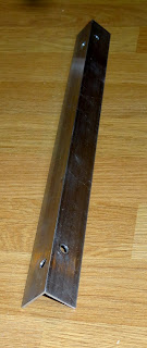
The two aluminium angle pieces are used to hold 4 bearings each. They will be screwed to  the underside of the X Axis table and will run along the rails.
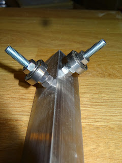
Each aluminium angle piece is 13 inches long and needs 4 holes drilling to fit bolts to hold the bearings. Note the holes are offset so the bolt heads don't overlap.


The details are shown in the two photos. The bolts used are 6mm. I have used 2 nuts against the aluminium angle then the bearing and a third nut. I also used washers on either side of the bearings but these may not be necessary. The bolts need to be shortened but I have left them like this for the time being as they do not affect the operation.


Note I pinched this method using the bearings and aluminium angle from the Instructables web site. The method was  posted on some excellent videos by Jason Welsh - "Build a CNC Machine" (cannedmushrooms).This is a link to the article


The above photos show how the bearings fit over the rails. The great thing about this method is there is no play from side to side.
The rails now screw to the bottom of the table (the table is 14 inches x 14 inches) using 2 screws for each.


X Axis Base and Rails

The base I have used is part of a kitchen worktop (we've recently had one fitted). The reason for using this is it is flat and fairly heavy to make a good solid base.
I have been reading a lot of other CNC sites and blogs and a lot of people use a metal base but since I had this worktop I am using it.


Base and X Axis parts


The X-Axis parts shown above are as follows:
Chrome plated steel tubes (these are mop handles from Poundstretcher!) they are 7/8 inch diameter
Aluminium angle from any DIY store - it is 1inch x 1inch
Pipe clips to hold the chrome tubes
Miniature bearings  - 7x19x6mm - from eBay
CNC table - just a piece of laminated chipboard .


Introduction

 
Home made CNC machine

I am starting this blog to document my attempt to build my own CNC machine for cutting wood plastic etc. controlled by a computer.
The above photo is a general photo from the web to give some idea of what the final machine will look like (hopefully).
A CNC (computer numeric control) machine uses some sort of cutting tool (probably a Dremel in my case) with the work piece able to be moved in X and Y directions to allow shapes to be cut. The Z axis is the up and down movement of the cutting tool to control the depth of cut and up and down movement start stop cut etc. The movement of each of the 3 axes are controlled by stepper motors which are connected to the computer via its USB or parallel ports.
I am building this machine as it combines several of my hobbies. I have worked most of my life as a software engineer but trained initially as an electrical engineer and I am a keen DIYer. It appeals to me to be able to use software to control something externally to produce useful items at the end of it.


I will record each step with photos (and possibly videos) and give as much info concerning dimensions, materials and building methods so anyone can use the ideas - I would welcome any comments, criticism, advice etc. as I go along.